Pages

Showing posts with label audio. Show all posts

Sunday, July 29, 2012

22 Watt Audio Amplifier Circuit

The 22 watt amp is easy to build, and very inexpensive. The circuit can be used as a booster in a car audio system, an amp for satellite speakers in a surround sound or home theater system, or as an amp for computer speakers. The circuit is quite compact and uses only about 60 watts. The circuit is not mine, it came from Popular Electronics.
Circuit diagram
22 Watt Audio Amplifier Circuit
Parts
R1 39K 1/4 Watt Resistor
C1,C2 10uf 25V Electrolytic Capacitor
C3 100uf 25V Electrolytic Capacitor
C4 47uf 25V Electrolytic Capacitor
C5 0.1uf 25V Ceramic Capacitor
C6 2200uf 25V Electrolytic Capacitor
U1 TDA1554 Two Channel Audio Amp Chip
MISC Heatsink For U1, Binding Posts (For Output), RCA Jacks (For Input), Wire, Board
Notes
1. The circuit works best with 4 ohm speakers, but 8 ohm units will do.
2. The circuit dissipates roughly 28 watts of heat, so a good heatsink is necessary. The chip should run cool enough to touch with the proper heatsink installed.
3. The circuit operates at 12 Volts at about 5 Amps at full volume. Lower volumes use less current, and therefore produce less heat.
4. Printed circuit board is preferred, but universal solder or perf board will do. Keep lead length short.

18W Audio Amplifier Circuit

circuit diagram
18W Audio Amplifier Circuit
Amplifier parts:
P1 = 22K Log.Potentiometer (Dual-gang for stereo)
R1 = 1K 1/4W Resistor
R2 = 4K7 1/4W Resistor
R3 = 100R 1/4W Resistor
R4 = 4K7 1/4W Resistor
R5 = 82K 1/4W Resistor
R6 = 10R 1/2W Resistor
R7 = R22 4W Resistor (wire wound)
R8 = 1K 1/2W Trimmer Cermet (optional)
C1 = 470nF 63V Polyester Capacitor
C2,C5 = 100uF 3V Tantalum bead Capacitors
C3,C4 = 470uF 25V Electrolytic Capacitors
C6 = 100nF 63V Polyester Capacitor
D1 = 1N4148 75V 150mA Diode
IC1 = TLE2141C Low noise,high voltage,high slew-rate Op-amp
Q1 = BC182 50V 100mA NPN Transistor
Q2 = BC212 50V 100mA PNP Transistor
Q3 = TIP42A 60V 6A PNP Transistor
Q4 = TIP41A 60V 6A NPN Transistor
J1 RCA audio input socket
Power supply parts:
R9 = 2K2 1/4W Resistor
C7,C8 = 4700uF 25V Electrolytic Capacitors
D2 100V 4A Diode bridge
D3 5mm. Red LED
T1 220V Primary, 15 + 15V Secondary 50VA Mains transformer
PL1 Male Mains plug
SW1 SPST Mains switch
Notes:
Can be directly connected to CD players, tuners and tape recorders.
Don't exceed 23 + 23V supply.
Q3 and Q4 must be mounted on heat sink.
D1 must be in thermal contact with Q1.
Quiescent current (best measured with an Avo-meter in series with Q3 Emitter) is not critical.
Adjust R3 to read a current between 20 to 30 mA with no input signal.
To facilitate current setting add R8 (optional).
A correct grounding is very important to eliminate hum and ground loops. Connect in the same point the ground sides of J1, P1, C2, C3 &C4. Connect C6 at the output ground.
Then connect separately the input and output grounds at the power supply ground.
Technical data:
Output power: 18 Watt RMS @ 8 Ohm (1KHz sine wave)
Sensitivity: 150mV input for 18W output
Frequency response: 30Hz to 20KHz -1dB
Total harmonic distortion @ 1KHz: 0.1W 0.02% 1W 0.01% 5W 0.01% 10W 0.03%
Total harmonic distortion @10KHz: 0.1W 0.04% 1W 0.05% 5W 0.06% 10W 0.15%
Unconditionally stable on capacitive loads
Author:
website: http://www.redcircuits.com/

10W Mini Audio Amplifier Circuit

finished device
10W Mini Audio Amplifier Circuit
Componets Layout

PCB

Componets List
R1 : 6 Ohm
R2 : 220 Ohm
R3 : nothing
R4 : 10 KOhm pontesiometer
C1 : 2200 uF / 25V
C2 : 470 uF / 16V
C3 : 470 nF / 63V
C4 : 100 nF
C5 : nothing
C6 : nothing
IC1 : TDA 2003
Author:
website: http://www.electronics-lab.com/

60W Bass Amplifier Circuit

Low-cut and Bass controls
Output power: 40W on 8 Ohm and 60W on 4 Ohm loads
Amplifier circuit diagram:
60W Bass Amplifier Circuit
Amplifier parts:
R1 6K8 1W Resistor
R2,R4 470R 1/4W Resistors
R3 2K 1/2W Trimmer Cermet
R5,R6 4K7 1/2W Resistors
R7 220R 1/2W Resistor
R8 2K2 1/2W Resistor
R9 50K 1/2W Trimmer Cermet
R10 68K 1/4W Resistor
R11,R12 R47 4W Wirewound Resistors
C1,C2,C4,C5 47�F 63V Electrolytic Capacitors
C3 100�F 25V Electrolytic Capacitor
C6 33pF 63V Ceramic Capacitor
C7 1000�F 50V Electrolytic Capacitor
C8 2200�F 63V Electrolytic Capacitor (See Notes)
D1 LED Any type and color
D2 Diode bridge 200V 6A
Q1,Q2 BD139 80V 1.5A NPN Transistors
Q3 MJ11016 120V 30A NPN Darlington Transistor (See Notes)
Q4 MJ11015 120V 30A PNP Darlington Transistor (See Notes)
SW1 SPST Mains switch
F1 4A Fuse with socket
T1 220V Primary, 48-50V Secondary 75 to 150VA Mains transformer
PL1 Male Mains plug
SPKR One or more speakers wired in series or in parallel. Total resulting impedance: 8 or 4 Ohm. Minimum power handling: 75W
Preamplifier circuit diagram:

Preamplifier parts:
P1 10K Linear Potentiometer
P2 10K Log. Potentiometer
R1,R2 68K 1/4W Resistors
R3 680K 1/4W Resistor
R4 220K 1/4W Resistor
R5 33K 1/4W Resistor
R6 2K2 1/4W Resistor
R7 5K6 1/4W Resistor
R8,R18 330R 1/4W Resistors
R9 47K 1/4W Resistor
R10 18K 1/4W Resistor
R11 4K7 1/4W Resistor
R12 1K 1/4W Resistor
R13 1K5 1/4W Resistor
R14,R15,R16 100K 1/4W Resistors
R17 10K 1/4W Resistor
C1,C4,C8,C9,C10 10�F 63V Electrolytic Capacitors
C2 47�F 63V Electrolytic Capacitor
C3 47pF 63V Ceramic Capacitor
C5 220nF 63V Polyester Capacitor
C6 470nF 63V Polyester Capacitor
C7 100nF 63V Polyester Capacitor
C11 220�F 63V Electrolytic Capacitor
Q1,Q3 BC546 65V 100mA NPN Transistors
Q2 BC556 65V 100mA PNP Transistor
J1,J2 6.3mm. Mono Jack sockets
SW1 SPST Switch
Circuit description:
This design adopts a well established circuit topology for the power amplifier, using a single-rail supply of about 60V and capacitor-coupling for the speaker(s). The advantages for a guitar amplifier are the very simple circuitry, even for comparatively high power outputs, and a certain built-in degree of loudspeaker protection, due to capacitor C8, preventing the voltage supply to be conveyed into loudspeakers in case of output transistors' failure.
The preamp is powered by the same 60V rails as the power amplifier, allowing to implement a two-transistors gain-block capable of delivering about 20V RMS output. This provides a very high input overload capability.
Technical data:
Sensitivity:
70mV input for 40W 8 Ohm output
63mV input for 60W 4 Ohm output
Frequency response:
50Hz to 20KHz -0.5dB; -1.5dB @ 40Hz; -3.5dB @ 30Hz
Total harmonic distortion @ 1KHz and 8 Ohm load:
Below 0.1% up to 10W; 0.2% @ 30W
Total harmonic distortion @ 10KHz and 8 Ohm load:
Below 0.15% up to 10W; 0.3% @ 30W
Total harmonic distortion @ 1KHz and 4 Ohm load:
Below 0.18% up to 10W; 0.4% @ 60W
Total harmonic distortion @ 10KHz and 4 Ohm load:
Below 0.3% up to 10W; 0.6% @ 60W
Bass control:
Fully clockwise = +13.7dB @ 100Hz; -23dB @ 10KHz
Center position = -4.5dB @ 100Hz
Fully counterclockwise = -12.5dB @ 100Hz; +0.7dB @ 1KHz and 10KHz
Low-cut switch:
-1.5dB @ 300Hz; -2.5dB @ 200Hz; -4.4dB @ 100Hz; -10dB @ 50Hz
Notes:
The value listed for C8 is the minimum suggested value. A 3300�F capacitor or two 2200�F capacitors wired in parallel would be a better choice.
The Darlington transistor types listed could be too oversized for such a design. You can substitute them with MJ11014 (Q3) and MJ11013 (Q4) or TIP142 (Q3) and TIP147 (Q4).
T1 transformer can be also a 24 + 24V or 25 + 25V type (i.e. 48V or 50V center tapped). Obviously, the center-tap must be left unconnected.
SW1 switch inserts the Low-cut feature when open.
In all cases where Darlington transistors are used as the output devices it is essential that the sensing transistor (Q2) should be in as close thermal contact with the output transistors as possible. Therefore a TO126-case transistor type was chosen for easy bolting on the heatsink, very close to the output pair.
R9 must be trimmed in order to measure about half the voltage supply from the positive lead of C7 and ground. A better setting can be done using an oscilloscope, in order to obtain a symmetrical clipping of the output waveform at maximum output power.
To set quiescent current, remove temporarily the Fuse F1 and insert the probes of an Avo-meter in the two leads of the fuse holder.
Set the volume control to the minimum and Trimmer R3 to its minimum resistance.
Power-on the circuit and adjust R3 to read a current drawing of about 30 to 35mA.
Wait about 15 minutes, watch if the current is varying and readjust if necessary.
author:RED Free Circuit Designs,
website: http://www.redcircuits.com/

10W Audio Amplifier with Bass-boost Circuit

circuit diagram
 
Parts:
P1 22K Log.Potentiometer (Dual-gang for stereo)
P2 100K Log.Potentiometer (Dual-gang for stereo)
R1 820R 1/4W Resistor
R2,R4,R8 4K7 1/4W Resistors
R3 500R 1/2W Trimmer Cermet
R5 82K 1/4W Resistor
R6,R7 47K 1/4W Resistors
R9 10R 1/2W Resistor
R10 R22 4W Resistor (wirewound)
C1,C8 470nF 63V Polyester Capacitor
C2,C5 100uF 25V Electrolytic Capacitors
C3,C4 470uF 25V Electrolytic Capacitors
C6 47pF 63V Ceramic or Polystyrene Capacitor
C7 10nF 63V Polyester Capacitor
C9 100nF 63V Polyester Capacitor
D1 1N4148 75V 150mA Diode
IC1 NE5532 Low noise Dual Op-amp
Q1 BC547B 45V 100mA NPN Transistor
Q2 BC557B 45V 100mA PNP Transistor
Q3 TIP42A 60V 6A PNP Transistor
Q4 TIP41A 60V 6A NPN Transistor
J1 RCA audio input socket
Power supply parts:
R11 1K5 1/4W Resistor
C10,C11 4700uF 25V Electrolytic Capacitors
D2 100V 4A Diode bridge
D3 5mm. Red LED
T1 220V Primary, 12 + 12V Secondary 24-30VA Mains transformer
PL1 Male Mains plug
SW1 SPST Mains switch
Comments:
This design is based on the 18 Watt Audio Amplifier, and was developed mainly to satisfy the requests of correspondents unable to locate the TLE2141C chip. It uses the widespread NE5532 Dual IC but, obviously, its power output will be comprised in the 9.5 - 11.5W range, as the supply rails cannot exceed �18V.
As amplifiers of this kind are frequently used to drive small loudspeaker cabinets, the bass frequency range is rather sacrificed. Therefore a bass-boost control was inserted in the feedback loop of the amplifier, in order to overcome this problem without quality losses. The bass lift curve can reach a maximum of +16.4dB @ 50Hz. In any case, even when the bass control is rotated fully counterclockwise, the amplifier frequency response shows a gentle raising curve: +0.8dB @ 400Hz, +4.7dB @ 100Hz and +6dB @ 50Hz (referred to 1KHz).
Notes:
Can be directly connected to CD players, tuners and tape recorders.
Schematic shows left channel only, but C3, C4, IC1 and the power supply are common to both channels.
Numbers in parentheses show IC1 right channel pin connections.
A log type for P2 ensures a more linear regulation of bass-boost.
Don't exceed 18 + 18V supply.
Q3 and Q4 must be mounted on heatsink.
D1 must be in thermal contact with Q1.
Quiescent current (best measured with an Avo-meter in series with Q3 Emitter) is not critical.
Set the volume control to the minimum and R3 to its minimum resistance.
Power-on the circuit and adjust R3 to read a current drawing of about 20 to 25mA.
Wait about 15 minutes, watch if the current is varying and readjust if necessary.
A correct grounding is very important to eliminate hum and ground loops. Connect in the same point the ground sides of J1, P1, C2, C3 &C4. Connect C9 at the output ground.
Then connect separately the input and output grounds at the power supply ground.
Technical data:
Output power: 10 Watt RMS @ 8 Ohm (1KHz sinewave)
Sensitivity: 115 to 180mV input for 10W output (depending on P2 control position)
Frequency response: See Comments above
Total harmonic distortion @ 1KHz: 0.1W 0.009% 1W 0.004% 10W 0.005%
Total harmonic distortion @ 100Hz: 0.1W 0.009% 1W 0.007% 10W 0.012%
Total harmonic distortion @10KHz: 0.1W 0.056% 1W 0.01% 10W 0.018%
Total harmonic distortion @ 100Hz and full boost: 1W 0.015% 10W 0.03%
Max. bass-boost referred to 1KHz: 400Hz = +5dB; 200Hz = +7.3dB; 100Hz = +12dB; 50Hz = +16.4dB; 30Hz = +13.3dB
Unconditionally stable on capacitive loads
author:RED Free Circuit Designs,
website: http://www.redcircuits.com/

Friday, July 6, 2012

100W Audio Amplifier

General Description

This is an exceptionally well designed amplifier, with a lot of power reserve, high fidelity, low distortion, good S/N ratio, high sensitivity, low consumption and full protection. Having all these almost ideal characteristics this amplifier is likely to become the basic building block of your future high fidelity system, or it can also become the element that will upgrade your existing system.

How it Works

The circuit works from a symmetrical СЃ40 VDC power supply and draws a maximum current of 2.6 A. The input circuit of the amplifier is a differential amplifier built around Q4 and Q5 that employ DC feedback thus preventing any DC voltage from appearing across the speaker with the usual destructive results. Q11 acts as a current source and ensures that the input stage draws a constant current of 1 mA. The signal which appears as a voltage drop across the resistor connected in series with the collector of Q4 is used to drive the DARLINGTON pair Q3, Q2 which together with the constant current source of 7 mA that is Q10, form the driver stage. This stage operates in class A and is driving the complementary output stage Q1, Q9. The transistor Q7 is used to balance the circuit at different temperatures and must be mounted on the heatsink between the out put transistors. The feedback loop which consists of R8, R9, C2, C3 provides AC stability to the circuit. The circuit also incorporates a protection stage that makes it virtually indestructible. This protection circuit is built around Q6, Q8. If for whatever reason the output remains connected on one supply rail and the common the output is also protected from high DC voltages that could burn the speakers. The supply rails should be protected by 2 A fuses for the 8 ohm version and 3 A for the 4 ohm.
100W Audio Amplifier


Technical Specifications - Characteristics

Output power (f=1 KHz, d=0.5 %): 100 W in 8 ohm
Supply voltage: ................ СЃ 40 V
Quiescent current: ............. 50 mA
Maximum current: ............... 2.6 A
Sensitivity: . 600 mV
Frequency response: ............ 10-35000 Hz (-1 dB)
Distortion HD: ................. 0.01 %
Intermodulation dist.: ......... 0.02 %
Signal/noise: 83 dBConstruction


PLEASE READ THIS BEFORE YOU START CONSTRUCTION
To cater for those who wish to use 4 ohm speakers with this amplifier the Kit includes the necessary components for both versions. The components that differ are R3,4,17 and 23. If you build the 8 ohm version then you must also include in the circuit R28 and D7, D8 which are not used in the 4 ohm version. As you see all the components are already marked on the component side of the p.c. board. The construction is made this way much simpler. Start the construction from the pins and the jumper connections, continue with the resistors and the capacitors and last solder in place the semiconductors. Check each resistor before soldering it, to see if
its colours match those in the component list. Be careful with the electrolytic capacitors because their polarity should be respected. The polarity of those capacitors is marked on their bodies and on the component side of the p.c. board.
NOTE: On the p.c. board next to R2, R16 are marked two other resistors which do not appear in the circuit diagram but are included in the components. They are of 1 ohm 2 W (brown, black, gold) and must be included in the circuit. Take care when you are soldering the semiconductors because if you overheat them they can be damaged. The output transistors should be mounted on the heatsink that is included in the kit. Take care not to short circuit them with the heatsink and we
recommend that you use some HTC between the transistor body and the sink in order to improve heat dissipation. Follow the diagram for the mounting of the power transistors as it shows clearly how to insert the insulators and the screws. Q7 should be made to touch the heatsink and is a good idea to use a bit of HTC between its casing and the surface of the heatsink. When you finish the construction of your project clean the board thoroughly with a solvent to remove all flux residues and make a careful visual inspection to make sure there are no mistakes, components missing and short circuits across adjacent tracks on the board. If everything is OK you can make the following connections: Input: 3 (signal), 5 (common) Output: 7 (signal), 6 (common) Supply: 1 (-40 VDC), 2 (+40 VDC) 5 (0 VDC)

Connect a milliammeter in series with the power supply, short the input of the amplifier, turn the power ON and adjust the trimmer P1 so that the quiescent current is about 50 mA. When you finish this adjustment remove the shunt from the input and connect the output of a preamplifier to it. Connect the pre amplifier to a suitable source and turn everything ON. The signal should be heard from the speakers clear and undistorted. First of all let us consider a few basics in building electronic circuits on a printed circuit board. The board is made of a thin insulating
material clad with a thin layer of conductive copper that is shaped in such a way as to form the necessary conductors between the various components of the circuit. The use of a properly designed printed circuit board is very desirable as it speeds construction up considerably and reduces the possibility of making errors. Smart Kit boards also come pre-drilled and with the outline of the components and their identification printed on the component side to make construction easier. To protect the board during storage from oxidation and assure it gets to you in perfect condition the copper is tinned during manufacturing and covered with a special varnish that protects it from getting oxidised and makes soldering easier. Soldering the components to the board is the only way to build your circuit and from the way you do it depends greatly your success or failure. This work is not very difficult and if you stick to a few rules you should have no problems. The soldering iron that you use must be light and its power should not exceed the 25 Watts. The tip should be fine and must be kept clean at all times. For this purpose come very handy specially made sponges that are kept wet and from time to time you can wipe the hot tip on them to remove all the residues that tend to accumulate on it. DO NOT file or sandpaper a dirty or worn out tip. If the tip cannot be cleaned, replace it. There are many different types of solder in the market and you should choose a good quality one that contains the necessary flux in its core, to assure a perfect joint every time.
DO NOT use soldering flux apart from that which is already included in your solder. Too much flux can cause many problems and is one of the main causes of circuit malfunction. If nevertheless you have to use extra flux, as it is the case when you have to tin copper wires, clean it very thoroughly after you finish your work. In order to solder a component correctly you should do the following:

- Clean the component leads with a small piece of emery paper. - Bend them at the correct distance from the component body and insert the component in its place on the board.


- You may find sometimes a component with heavier gauge leads than usual, that are too thick to enter in the holes of the p.c. board. In this case use a mini drill to enlarge the holes slightly. Do not make the holes too large as this is going to make soldering difficult afterwards.


- Take the hot iron and place its tip on the component lead while holding the end of the solder wire at the point where the lead emerges from the board. The iron tip must touch the lead slightly above the p.c. board.

- When the solder starts to melt and flow, wait till it covers evenly the area around the hole and the flux boils and gets out from underneath the solder. The whole operation should not take more than 5 seconds. Remove the iron and leave the solder to cool naturally without blowing on it or moving the component. If everything was done properly the surface of the joint must have a bright metallic finish and its edges should be smoothly ended on the component lead and the board track. If the solder looks dull, cracked, or has the shape of a blob then you have made a dry joint and you should remove the solder (with a pump, or a solder wick) and redo it.

- Take care not to overheat the tracks as it is very easy to lift them from the board and break them.
- When you are soldering a sensitive component it is good practice to hold the lead from the component side of the board with a pair of long-nose pliers to divert any heat that could possibly damage the component.

- Make sure that you do not use more solder than it is necessary as you are running the risk of short-circuiting adjacent tracks on the board, especially if they are very close together.


- When you finish your work cut off the excess of the component leads and clean the board thoroughly with a suitable solvent to remove all flux residues that still remain on it.


parts:

Thursday, July 5, 2012

Amplifier 2x30W with STK465 Circuit

A amplifier of acoustic frequencies can be manufactured with discernible materials, despite is known so much the difficulties of finding of materials, what the problem of regulations. These difficulties are overcome relatively easily if we find amplifier in form completed.
Completed STK465 is an amplifier of acoustic frequencies that offers qualitative output, using minimal exterior elements. Substantially he is one of big completed force. Has a line pins and incorporated metal surface for adaptation in cooler. The provision pins in a line, facilitates the placement completed in the end printed and his support in cooler. The circuit functions in a big range of benefits of catering, from 20V as 60V, and it attributes 30WRMS, when the tendency of catering is above 50V and composer resistance of loudspeaker is the 4 or 8 Ohm. The catering should be symmetrically.
When it functions with tendency 56V then the tendency will be � 28V as for the ground. With this recommended tendency of catering, the attributed force is 30 WRMS in charge 8W. The price of deformity is acceptable and oscillates around in the 0,08% for force of expense from 1W until 30W. Curve response his it is extended from 10Hz and reaches 100 KHz, with divergence 0dB and -3dB respectively, measured in force 1W. Using evolved techniques, completed amplifier STK465, can minimise the deformities even in highest levels of force. Other characteristically that determines the completed circuit they are: the wide area and the high aid.
Schematic
STK465 is drawn to be constant, when it functions in conjunction closed bronchi with big gain. As all the amplifiers, thus and this, under certain unfavourable conditions, can turn in oscillations. These oscillations have as result of returning in the same phase from the exit in the entry, or from bad designing PCB, or from bad choice of corridors in the circuits of entry. When you draw a printed circuit, it is important to return the current of charge and the current of signal of entry in the ground, via different corridors. Generally, positive is the charge it is connected directly in pin the catering and in particular in common pin electrolytic the catering. If entry and charge are connected directly in the 0V via the same road, then are created retroactions, what have as consequence oscillations and the deformity. To you we propose maintaining as much as possible smaller the cables of ground 0V and the capacitors of unharnessing, so that are limited the results of self-induction and resistance of lines of copper PCB. Sometimes the oscillation is owed in big length drivers between entry and expense, particularly if these have big length and the complex resistance of source are high. Can anticipate the oscillation that is owed in long wirings, adding capacitor from 50 - 500pf between pins entry. For the low deformity, important role plays also the placement of conductors of catering. This should be kept as much as possible more far from the wiring of entry, so that is deterred thus the not linear catering in the entry of IC. STK 465 does not have system of thermal protection, so that are avoided the thermal elations. If the temperature of JC reaches in high price, then the amplifier changes the polarisation of rung of expense. If the temperature is increased, then in order to is ensured the operation it should you grow cooler. The amplifier functions with catering of double polarity. In form 1 we see the electronic circuit of amplifier that Is based on the STK 465.
The circuit is stereo and has two channels of amplifier in a nutshell. It is a formal designing that develops positively all the particularities completing. Concretely, we observe that the not inverting entry completed (pins 2 and 15, for each channel), is supplied from divider of tendency, which ensures tendency from the tendency of expense completing. At the same time with the entry in each channel, exists a capacitor 470rF, which achieves the unharnessing, in that it concerns the AC components of high frequency, while en line a capacitor 1mF allows in the amplifier to be supplied from desirable flourish acoustic frequencies, fence simultaneous the continuous component. Bronchi unharnessing it is realised with the help of networking of two resistances 33KW and 330W and a capacitor 100mF, which finally ensures factor of aid equal with 100. Finally, at the same time with the exit exists networking RC (0,1mF - 4,7 Ohm) that it attends to the minimisation of phenomenon crossover. The amplifier can be supplied from a line of double polarity. Still it can function under a wide region of tendencies (�10V as �28V). The requirements of current depend from the force of expense and it can they begin from 120mA up to 1A. It is very important the catering to be sufficiently unharnessing, so that is avoided imports of annoying noises.
The manufacture by Soylis Papanastasioy
For the realisation of manufacture you are consulted the forms 2 and 3 that portray the PCB and placement of materials in this. Does not exist a dangerous element in the manufacture that it should him you are careful particularly, so much at the soldering, what at the use. Be careful the electrolytic capacitors, the placement cooler completed and naturally the polarity of lines of catering. One still directive in what it concerns the catering: good it is it is used power supply with big capacitors standardisation or still better stabilised.
parts
R1 = 1K
C1 = 1uF/35V
R2 = 3,3K
C2 = 470pF
R3 = 100
C3 = 100uF/60V
R4 = 330
C4 = 100uF/60V
R5 = 3,3K
C5 = 10uF/60V
R6 = 1K
C6 = 47uF/60V
R7 = 0,33
C7 = 8,2pF
R8 = 33k
C8 = 0,1uF
R9 = 4,7
C9 = 1uF/35V
R10 = 1k
C10 = 470pF
R11 = 3,3k
C11 = 100uF/60V
R12 = 100
C12 = 100uF/60V
R13 = 330
C13 = 10uF/60V
R14 = 3,3k
C14 = 47uF/60V
R15 = 1k
C15 = 8,2pF
R16 = 0,33
C16 = 0,1uF
R17 = 33k
R18 = 4,7
IC1 = STK465
LS1 = Speaker 40W 8 or 4 Ohm

Wednesday, July 4, 2012

150W MP3 Car Amplifier

Block Diagram:
Here, it is a diagramm of an active loudspeaker. The LF353 of, National Semiconductor, is going to split audio signal into three bands. SANYO'S LA47536 is going to amplify these signals. In stereo mode, we shall have the action of eight high speakers who are going to create a very important sound pressure.
Description :
LF353 Wide Bandwidth Dual JFET Input Operational Amplifier
General Description
These devices are low cost, high speed, dual JFET input operational amplifiers with an internally trimmed input offset voltage (BI-FET II technology). They require low supply current yet maintain a large gain band width product and fast slew rate. In addition, well matched high voltage JFET input devices provide very low input bias and offset currents. The LF353 is pin compatible with the standard LM1558 allowing designers to immediately upgrade e the overall performance of existing LM1558 and LM358 designs. These amplifiers may be used in applications such as high speed integrators, fast D/A converters, sample and hold circuits and many other circuits requiring low input offset voltage, low input bias current, high input impedance, high slew rate and wide bandwidth. The devices also exhibit low noise and offset voltage drift. (National Semiconductor)
Features :
Internally trimmed offset voltage: 10 mV
Low input bias current: 50pA
Low input noise voltage: 25 nV
Low input noise current: 0.01 pA
Wide gain bandwidth: 4 MHz
High slew rate: 13 V/us
Low supply current: 3.6 m
High input impedance: 1012.
Low total harmonic distortion : < 0.02%
Low 1/f noise corner: 50 Hz
Fast settling time to 0.01%: 2 us


When the amplifier is installed behind in the suitcase, we shall need a switch works stop. The LA47536 possesses a function stand by in it pin4. This pine require a small tension superior to 2V in start up the amplifier. Transistor Q1 and Q2 makes the function of walking stop for distance. When the driver activates the left indicator, either light the back fires or press on the brake , lamps rear ignite driving Q2 who he even made to drive Q1 who applies a tension > 2V on it pin4. Overview
LA47536 Four-Channel 45 W BTL Car Audio Power Amplifier
The LA47536 is a 4-channel BTL power amplifier IC developed for use in car audio systems. The output stage features
- A pure complimentary structure that uses V-PNP transistors on the high side and NPN transistors on the low side to provide high power and superb audio quality.
- The LA47536 includes almost all the functions required for car audio use, including a standby switch, a muting function, and each protection circuit. It also provides a self-diagnosis function (output offset detection). (Sanyo)
Functional Description
1. Standby Switch Function (pin 4)
The pin 4 threshold voltage is set to be 2 VBE. When Vst is 2.0V or higher, the amplifier will be on, and when Vst, is 0.7V or lower, the amplifier will be off. Note that pin 4 requires an operating current of at least 40uA.
2. Muting Function
The IC is set to the muted state by setting pin 22 to the ground potential. In this state, the audio output is muted. The time constant with which the muting function operates is set by an external RC circuit, and this time constant influences the pop noise that occurs when the amplifier is turned on or off.
The muting on and off times due to the recommended external component values (R=10k, C=3.3uF) are as follows.
Muting on time: 50ms
Muting off time: 20ms
3. Self-Diagnosis Function (Speaker burnout prevention)
During steady state operation, the LA47536 detects, internally, whether or not an abnormal amplifier output offset has occurred, and outputs this signal from pin 25. Applications can prevent speaker burnout and other problems by having the system microcontroller detect this pin 25 output signal and control either the standby state or the power supply. (An abnormal output offset may be caused by, for example, input capacitor leakage current.) The pin 25 signal is turned off by setting pin 1 to the ground potential.
4. Oscillator Stability
In some cases, parasitic oscillations may be induced by the PCB layout. This oscillation can be eliminated by adding the components listed below. Note that the optimal capacitor value must be verified by testing in the actual mounted state in the end product. Connect a capacitor and resistor (0.1uF and 2.2) in series between each output pin and ground.
5. Audio Quality (Low band)
The frequency characteristics in the low frequencies can be improved by making the capacitance of the input capacitors variable. The recommended capacitance is 2.2uF and smaller.
6. Protection Circuits
Do not ground the outputs with the STBY voltage at around 1.4V. Also, do not turn the IC off in the grounded state with a time constant provided for the STBY voltage.
7. Pop Noise
Although the LA47536 includes an pop noise prevention circuit, pop noise can be reduced even further by using the muting function as well. Activate the muting function at the same time as power is applied. Then, after the output DC potential has stabilized, turn off the muting function. When turning the amplifier off, first turn on the muting function and then turn off the power supply. These two methods are effective at minimizing pop noise.


Digital Volume Control Circuit

circuit diagram

Circuit of a digital volume control using six discrete ICs, including a 5V regulator, is presented. IC1 (555) is configured to function as astable flip-flop. Its frequency or period may be adjusted by proper choice of resistors R44, R45 and capacitor C6 combination. Here it is for 0.3 second period.
IC2 is a presetable up/down counter. In this circuit up-mode is used for increasing and down-mode is used for decreasing the volume. IC3 and IC4 are 16-channel analogue multiplexers which function as analogue switches. Here IC3 is used as level indicator while IC4 is used as a potentiometer.
Soon after the power is switched on, switch S1 is to be pressed to reset the whole system. When switch S2 is pressed, IC2 counts up the number of pulses and the result is available in the form of BCD output. IC6 is used as an interface between TTL and CMOS ICs. The BCD output controls the address input lines of IC2 and IC3, and selects/switches one, out of sixteen channels, by turning on the appropriate analogue switch.
In the circuit, IC4 is used as a potentiometer by connecting 15 resistors (R9 through R23) between each of its 16 input pins and a resistor/capacitor combination of C2, C3 and R7 at its output. The values of resistors R9 through R23 can, of course, be selected as desired. Here the resistors have been selected for a logarithmic scale.
Switch S2 is used for increasing and switch S3 is used for decreasing the volume. Similarly, switches S4 and S5 are provided for second channel (right channel) volume control. Also, pin 14 of IC2 can be connected to IC 74193 pin 14 (clear input) of the right channel volume control circuit. The volume control circuit of right channel will be identical to that of the left channel circuit (shown here) except that IC1, IC5 and push-to-on switches are not to be duplicated.
A 1uF electrolytic capacitor (C4) is used to prevent switching noise. Resistors R8 and R6 are used to fix the quiescent operating voltage level at half the supply voltage for avoiding distortion of the audio signal from the preamplifier. Capacitors C2, C3 and resistor R7 are provided for proper filtering of the audio and blocking DC component. An exact logarithmic scale of resistors R9 through R23 produces a pleasing and smooth control.

50 Watt Amplifier Circuit

circuit diagram

This is a handy, easy to build general purpose 50 watt amp. The amp has an input for a radio, TV, stereo or other line level device. It also has a phono input for a record player, guitar, microphone or other un-amplified source. With the addition of a low pass filter at the input, it makes a great amp for a small subwoofer.

parts
R1 200 Ohm 1/4 W Resistor
R2 200K 1/4 W Resistor
R3 30K 1/4 W Resistor
R5 1K 1/4 W Resistor
R6 5K 1/4 W Resistor
R7,R10 1 Meg (5%) 1/2 W Resistor
R8,R9 0.4 Ohm 5 W Resistor
R11 10K Pot
R12,R13 51K 1/4 W Resistor
R14 47K 1/4 W Resistor
C1 100uF 35V Electrolytic Capacitor
C2 0.011uF Capacitor
C3 3750pF Capacitor
C4,C6 1000pF Capacitor
C5,C7,C8 0.001uF Capacitor
C9 50pF Capacitor
C10 0.3uF Capacitor
C11,C12 10,000uF 50V Electrolytic Capacitor
U1,U2 741 Op Amp
U3 ICL8063 Audio Amp Transister Driver thingy
Q1 2N3055 NPN Power Transistor
Q2 2N3791 PNP Power Transistor

Monday, July 2, 2012

15 watt amplifier


Description:
A 15 watt amplifier made using discrete components. Sergio designed this circuit for his Electronics Level II course.
Notes:
This amplifier uses a dual 20 Volt power supply and delivers 15 watts RMS into an 8 ohm load. Q1 operates in common emitter, the input signal being passed to the bias chain consisting of Q8, Q9, D6, D13 and D14. Q8 and Q9 provide a constant current through the bias chain to minimize distortion, the output stage formed by a discrete darlington pair (Q2,Q4) and (Q7,Q11). The last two transistors are power Transitors, specifically the 2N3055 and MJ2955. The 7.02K resistor, R16 was made using a series combination of a 4.7K, 680 Ohms, and two 820 Ohms. The 1.1K resistor, R3 was made using a 100 Ohms and a 1K resistor. You can use this circuit with any walkman or CD player since it is designed to take a standard 500mv RMS signal.

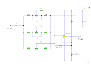
3 Band Graphic Equalizer


Notes
Using a single op-amp this easy to make equalizer offers three ranges, low frequency,mid frequency,and high. With component values shown there is approximately +/-20dB of boost or cut at frequencies of 50Hz, 1kHz and 10kHz. Supply voltage may be anything from 6 to 30 Volts. Maximum boost 20dB is only realized with maximum supply voltage.
Related Posts Plugin for WordPress, Blogger...

Popular Posts